Tadalafil zeichnet sich durch eine außergewöhnlich lange Halbwertszeit im Vergleich zu anderen PDE5-Inhibitoren aus. Diese pharmakokinetische Eigenschaft führt zu einer verlängerten Exposition des Wirkstoffs im Organismus. Die Eliminationsrate hängt von der hepatischen Aktivität des CYP3A4-Enzyms ab. Lipophile Eigenschaften unterstützen eine weite Verteilung in unterschiedlichen Geweben. Eine ausgeprägte Stabilität gegenüber Nahrungsaufnahme macht den Stoff besonders konstant in seiner Wirkung. Unter generischen Präparaten wird cialis online häufig mit einem vergleichbaren pharmakologischen Profil beschrieben.
P39_40_43_44_45_radcomjanuary1
PETER HART, G3SJX ♦ E-MAIL: PETER@G3SJX.FREESERVE.CO.UK
Kenwood TS-590SPeter Hart reviews the latest HF & 50MHz transceiver
which is a customised abbreviated menu list,
or by al ocating menu items to programmable
function keys. There are two programmable
function keys on the front panel and a further
four with the MC-47 microphone (available as
an optional extra). Alternatively, the up/down
with the radio can be reassigned as function
keys. Al menu items, second level key functions
and some otherwise inaccessible functions can
be assigned to any of the programmable keys.
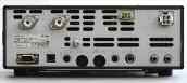
There are two antenna sockets on the rear
panel and there is also a separate receive-
only antenna connector. Key jacks are only
fit ed on the rear panel, one for connecting a
paddle to the internal keyer and a separate
socket for external keying. Other rear panel
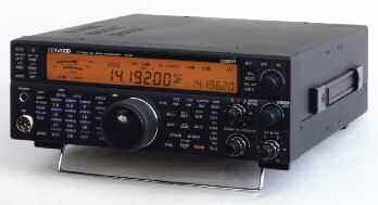
PHOTO 1: General view of the Kenwood TS-590S.
connectors are fairly minimal: a DIN connector
for audio and interfacing lines for the data
of the key forces in the design and supply
linear control. Menu items al ow for both
of amateur transceivers ever since these first
a triple band stacking register where one of
fast and slow linear switching separately for
three last used combinations of frequency,
HF and 50MHz but there is only one linear
mode and other set ings is returned for each
control line. A dedicated connector interfaces
the years and the excel ence of these designs
press of the band key. Individual but ons also
is borne out by the number that are stil in
select the usual modes, with both sidebands
For connecting to a PC, a USB interface and
use by their loyal and contented owners.
available on CW and FSK and wide or narrow
a 9-pin D connector COM port are provided.
deviations on FM. A data but on selects data
has reduced; indeed, it is now seven years
and for passing audio to and from external
since the last Kenwood HF transceiver so the
interfacing to PC applications (via the sound
applications. Software and port drivers are
announcement of a new model, the TS-590S, card); shifts and bandwidths al set able. Modes available from the Kenwood US website [1].
has (not surprisingly) been greeted with a great can be selected automatical y by set ing up a
amount of interest. Shortly after receiving the
built-in firmware is upgradeable. Again, ful
review radio I produced a short summary of
The front panel is wel laid out, with most
details are given on the Kenwood US website.
my first impressions for the December RadCom functions directly accessible from front panel
controls in a logical way. The display uses
with the radio is comprehensive and writ en
LCD technology with selectable yel ow or green
in a very compact style but in some cases is
LED backlighting. It is clear and bright with a
not particularly clear. There are no technical
good viewing angle. It also retains excel ent
descriptions, circuit diagrams or CAT details
visibility in bright lighting or direct sunlight,
is suf iciently smal to be easily transportable
unlike many other display technologies.
downloadable from the Kenwood website.
but of adequate size to be comfortable to
A further five instruction manuals in dif erent
operate. The radio requires a 13.8V supply.
and receiver filter bandwidths are similarly
languages are provided with the radio, which
It contains a single receiver tuning 30kHz
shown as a graphical bar. A separate but on
to 60MHz, although the performance is not
displays filter bandwidths and shifts numerical y
specified over the ful range. The transmit er
for about 1 second. The frequency is displayed
is enabled on the amateur bands and delivers
to 10Hz resolution and both frequencies are
The receiver in the TS-590S uses a rather
displayed for split frequency operation.
novel architecture. Over most of the tuning
operation on 5MHz is standard in US models
range it is a triple conversion superhet, up-
but can be enabled by Kenwood dealers in the
with 88 items and is easy to access and set. It converting to a first IF of 73MHz, then to the
UK. This gives continuous transmit coverage
uses scrol ing display annotation. Two entirely second IF of 10.7MHz and final y to 24kHz
across the 5MHz band for al modes but the
separate sets of parameters may be stored, as
to feed the DSP. A 15kHz bandwidth roofing
discrete channels are best stored to memory
Menu A and Menu B. This can be useful for
filter is fit ed at the 73MHz IF with 15kHz,
for easy access. A low-level drive output is
optimising dif erent operating environments
provided giving about 1mW transmit signal
such as contesting and local rag-chewing or
for field day operation where two operators
bandwidth. On certain amateur bands (160,
drive from any of the HF bands. The low level
have dif erent preferences for the way the radio 80, 40, 20 and 15m) and with bandwidths
LF transmit range can be extended to 522kHz is set up. Access to selected menu items can
less than 2.7kHz a separate first mixer down-
with a dealer modification, useful if 500kHz
be simplified by set ing up a quick menu,
converts directly to the second IF, now at
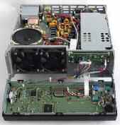
PHOTO 2: Top view with covers removed showing PA, output filters and
PHOTO 3: Underneath view showing signal processing boards.
double this value. On CW, FSK and SSB data
process. Narrow roofing filters of 2.7kHz or
modes these dual controls adjust bandwidth
500Hz bandwidth are selected automatical y
it combines precise tuning with fast frequency and centre frequency (shift). The default shift
in the down-conversion path, depending on
navigation. Fine-tuning at one tenth of these
rates is selectable, as are lower steps per
pitch frequency. Bandwidths are portrayed
revolution if desired. Rapid tuning in a variety
graphical y on the display but actual values
up-conversion path. A 32 bit floating-point
of mode-dependant step sizes is performed
are displayed for about one second at the
DSP is used to provide IF channel filtering,
by a smal click-step rotary control, which
push of a key. Bandwidth set ings are stored
is also used to select menu items, memory
separately for each mode. Two separate sets
channels and other functions. The frequency
there is an additional conversion from the
may be entered directly using the band keys
from a front panel key, the equivalent of
as a numeric keypad and a history list of the
normal/narrow set ings on other radios but
last 10 frequencies entered this way is stored
more versatile. There is no user access to the
audio to the DSP. On this mode the DSP is
roofing filter selection; this is set automatical y
used purely for audio filtering functions.
together with split frequency operation and
Four dif erent notch circuits are provided.
bipolar preamplifier with nominal y 12dB gain
a TFSET key for quick monitoring and tuning
the transmit frequency during split frequency
adjustable centre frequency and wide/narrow
is a switchable at enuator for real y strong
operation. RIT and XIT are both available
signal situations and 13 input bandpass filters
to give incremental tuning over a range of
covering the total frequency range of the receiver. ±10kHz. An auto-tune feature fine tunes
single interfering tone on SSB. Implemented
Both first mixers use a quad arrangement of
the receiver to give the correct CW pitch,
at audio are two beat cancel ation filters for
MOSFETs and the local oscil ator feeds are
but this is best avoided if there are any
interfering signals in the passband. There
remove multiple tones. This is the function
without the usual PLL. This can result in
normal y cal ed auto-notch on other radios.
a further 10 for storing programmable scan
One beat cancel ation filter is more ef ective on
low-level spurious outputs can be more of a
limits. The usual memory transfer functions
continuous beats and the other on intermit ent
problem. There is a normal crystal reference
are provided and name tags of up to eight
oscil ator but a 0.5ppm TCXO is available as an characters may be assigned. A separate quick functions are provided that use dif erent
optional extra. The transmit signal path uses
access memory is included, which stores up
algorithms and dif er in their ef ectiveness
the up-conversion frequency scheme in reverse. to 10 channels. Comprehensive scanning is
depending on the prevailing situation. Final y
provided between frequency limits, across
in the armoury for combating interference are
conventional style using a substantial diecast
two noise blankers. NB1 is a conventional IF
frame on which the circuit boards are mounted
Two dif erent methods are used to set the IF
together with a wrap-around case. A bail stand
channel bandwidth, depending on the mode,
tilts the front panel to improve visibility and
using dual concentric rotary controls. On SSB,
operating ease. Dual internal fans cool the PA, AM and FM, slope tuning is used, with separate
operating only when the temperature rises.
control of the low and high frequency cut-of s. a programmable decay time constant. There
There is substantial internal heatsinking so
The net bandwidth is the dif erence between
are no separate audio filters for CW or data
these fans rarely operate in normal use. A 7cm
the two. On AM and FM the quoted bandwidth
is somewhat misleading. On FM it relates to the enabled that has eight selectable profiles.
audio filtered bandwidth; the IF bandwidth is
fixed at 12kHz. On AM it also relates to the
audio bandwidth after demodulation but it
output is variable on al modes down to about
smooth in operation and with drag adjustment. is the IF bandwidth which is filtered to about
5W and can be set separately for the HF bands
later. The radio can also be control ed remotely
over a network or over the internet using the
uses the ARCP-590 at the operator (remote)
ARHP-590 host program running at the radio
end of the link and with audio lines carried
programmed from the separately using a protocol such as VOIP.
Kenwood does not supply the VOIP software,
which is readily available from other sources,
but the control and host software is freely
downloadable from the Kenwood website [1].
message stores can be access to the radio, perhaps from the garden
used to pass receive and transmit audio and
al control signals. In the USA other Kenwood
VHF/UHF models are also suitably equipped.
VHF/UHF packet cluster network by connecting
FIGURE 1: Composite selectivity curve on USB. Frequency is 1.9MHz.
radio and there are several Kenwood models
Black line - Rx1 bandwidth 2.3kHz, red line - Rx2 bandwidth 2.8kHz.
suitably equipped. Incoming cluster spots can
be passed to the TS-590S, which is then set
and 50MHz. This is useful if you use a linear
guide and message store is an optional extra.
I had the radio linked satisfactorily to the
The voice guide provides voice readout in
Logger32 logging program using the generic
output is indicated on the display meter,
English or Japanese of the status of various
Kenwood protocol for control of the radio and
radio set ings depending on how it has been
logging data and for passing DX Packet Cluster
level. The radio includes a built-in auto ATU
set up. This includes the frequency, meter
covering the bands 1.8 to 50MHz (including
readings and virtual y any other set ings and
5MHz) and wil tune antennas with up to 3:1
key presses and can be a great help for those
VSWR. The ATU can be set to be in circuit on
with impaired vision. The second use of this
measurements is given in the table. Sensitivity
option is to provide an audio store. This can be
measurements showed that the up-conversion
used to record up to two 30 second messages receive path Rx2 was slightly more sensitive
a transmission monitor are provided and the
than the down-conversion path Rx1 and had
audio bandwidth may be tailored by adjusting playback on air as CQ cal s or contest
about 2-3dB higher gain within the signal path.
the low cut and high cut response. In addition,
The receiver is very sensitive, particularly on
an audio equaliser may be enabled that has
record the receiver output continuously and
six selectable profiles. FM repeater operation
retain the last 30 seconds. This can be stored
has an extra 8dB of gain. The sensitivity holds
is best achieved by set ing the transmit and
receive frequencies in split operation and
cannot be played back on air and there is an
(preamp on) and only starts to reduce at 50kHz.
storing to memory together with the relevant
annoying delay of 20 seconds initial y whilst
Sensitivity is reduced by about 16dB over the
access tones. There is no direct repeater shift
the contents are stored to flash memory.
set ing. Rx/Tx tone decoders and encoders are
For use with transverters, the display can
calibration was moderately linear and showed
provided for CTCSS operation, which can use
be set to indicate the transverted frequency.
about 3dB per S unit. Al modes were the same,
Three digits are available for the MHz segment,
except FM which was highly compressed.
On CW the rise and fal times of the keying
eg 144 or 432. Of sets can be stored to a
envelope are set able from 1 to 6ms and there resolution of 100Hz. The transmit drive source
is the usual provision for ful and semi break-in.
for the transverter in most cases wil use the
Semi break-in drop back delay is adjustable
low-level 1mW drive output which disables
path these figures were typical y bet er than
the transmit er PA, but there is a menu option
90dB. I searched careful y for other spurious
set ing it is ful break-in. One useful feature
to use the PA at its lowest power level (5W).
responses as DDS circuits tend to be prone
if you often tune around in dif erent modes is
Make sure you avoid transmit ing into the
to this problem. Rx2 was very clean with no
the ability to select automatical y CW mode
transverter IF output when the transverter is
disabled by using the receive-only input on
exceptional y clean with no other responses
feature is to al ocate one function key for
less than 100dB down except an internal y
tune-up. This outputs a carrier, ir espective of
generated birdie on 1827.5kHz, just above
mode, at a power level that can be set separately
areas of communication linked with the PC
the noise level. In the most popular part of
from the normal transmit power level.
An electronic keyer is built in using a paddle similarly supported. Kenwood provides a
connected to the dedicated rear panel jack.
problem with ful -size antennas. However,
It operates over the speed range 4 - 60wpm.
enable access to virtual y al functions of the
with smal receive-only loops and Beverages
The speed in wpm is indicated on the display. radio from a PC running Windows XP SP3 or
it wil be an issue. Switching to Rx2 by selecting
a bandwidth greater than 2.7kHz makes this
The close-in strong signal performance is
limited in some cases by the AGC. A somewhat
Ukranian DX Contests. The receiver performed
complex AGC system is used, detecting signal
very wel : sensitive and lively on the quieter
level in three places within the DSP signal
bands, it coped wel picking out weak signals
amongst strong signals and QRM on the lower
channel selectivity. Hence a strong signal
PHOTO 5: The front panel hinged down showing
bands. I could not detect any real dif erence in
fal ing inside the roofing filters but stil
performance on-air between the up-conversion
outside of the final channel filter wil result
in AGC action, reducing gain and sensitivity
conditions I experienced at the time. The audio
and result in blocking. This can be heard as
quality using the internal speaker was excel ent
a quietening of the receiver from a very strong
measured for Rx1 are excel ent, similar to
signal just outside of the channel passband.
or bet er than top-end radios costing two to
performance extended down to LF, with the
The ef ect is most noticeable with the wider
time-code transmissions and was also good
roofing filters and is not an issue with the
is best on the lower bands. For Rx2 the RM
in the AM broadcast bands. The receiver birdie
500Hz roofing filter in circuit. In other
performance is fairly average, similar across
respects the AGC performance was general y
the bands and nowhere near as good as Rx1.
160m receive loop and significantly stronger
clean but the at ack response inserted a hole
This is surprising considering it is the same
than the ZL8X DXpedition that was active on
of up to 10ms in the signal. This is seen in
the hole was not as deep as in some radios
results, it was possible to measure over 80dB
down the channel filter skirts in some cases
(500Hz), although AGC was having an ef ect
figures on dif erent bands for Rx1 and Rx2.
where the wider roofing filters were in circuit.
dif erent from the noise reduction systems
The table shows the results down to 60dB,
on other radios. They could be very ef ective
bands use Rx2. For bands that use Rx1 the
which are fairly typical for DSP filters. Figure 1
in certain circumstances and quite aggressive
shows the composite selectivity curve on USB in operation but tended to produce a digital
bandwidth. The results show excel ent front-
for Rx1 and Rx2. The skirt widening with Rx2
sound with strange artefacts if overdone.
is due to AGC close-in and reciprocal mixing
reported as being excel ent using the supplied
On transmit, two-tone distortion products
microphone and the processor was clean and
were particularly low for a 12V operated PA and added extra punch. The default microphone
the processor was very clean with negligible
gain set ing is a bit on the high side and
the 2.7kHz bandwidth filter at the second
ef ect on wideband products. The audio was
IF (15kHz bandwidth filter at the first IF).
very clean with low distortion and most tolerant the sidetone were clean and wel behaved.
The results for Rx1 are real y excel ent,
of high ALC levels and overdrive. The auto ATU
reduced power by about 10 to 15%. CW rise
spacing and 90dB at 1kHz. The results for
and fal shapes were clean with negligible
distortion or character shortening at 40wpm,
real y useful features, easy to operate with
filters. At spacings below 10kHz the dynamic
even in ful break-in mode. There was a 15ms
wel thought out and friendly ergonomics.
range reduces by around 10dB as the signals
delay on keying. AM transmit was clean with
The performance on the key five bands where
approach the first IF filter passband. Then at
it is a down-conversion radio is equal to the
2kHz and below the signals enter the second
best radios available but at a fraction of the
IF filter passband: AGC takes ef ect (see
ON THE AIR PERFORMANCE. Over the period price. Even on the other bands it returns a
that I had the radio for review, I came to real y
meaningful measurements cannot be made.
like the ergonomics and appreciate the thought
that Kenwood has put into implementing the
general y available with a significant discount
front-end can handle very strong signals.
various functions and features in a user-
and at this price it is excel ent value for money.
Close-in, the ef ects of the roofing filters can
friendly way. The tuning is smooth and positive,
be clearly seen and signal handling reduces,
display clear and bright and functions easy to
although Rx1 with the 500Hz filter maintains
access. The dual rotary controls are a bit smal
express my gratitude to Kenwood Electronics
excel ent blocking performance down to 1kHz and fiddly but this is inevitable in a radio of this UK for the loan of this radio.
spacing (where reciprocal mixing noise starts
size. The bandwidth set ing controls are a lit le
to be seen). With the 2.7kHz roofing filter
confusing, with CW bandwidth and SSB high
[1] Kenwood USA website for software downloads:
cut on opposite controls, but it is something
0.28µV (-118dBm) 0.08µV (-129dBm) 40µV
100dB above AGC threshold for <1dB audio output increase
Max audio at 1% distortion: 1.8W into 8 ohm
Inband intermodulation products: -45 to -55dB
INTERMODULATION (50kHz SPACING) ON USB. BANDWIDTH 2.3kHz (Rx1) 2.8kHz (Rx2)
---Rx1 PREAMP OFF--- ---Rx1 PREAMP ON--- ---Rx2 PREAMP OFF--- ---Rx2 PREAMP ON---
CLOSE-IN INTERMODULATION ON CW WITH 500Hz
RECIPROCAL MIXING 500Hz BW ------------ BLOCKING PREAMP OFF ------------
Intermodulation product levels are quoted
Transmit er AF distortion: Less than 0.1%
wide SSB T/R switch speed: mute-Tx 15ms,
Al signal input voltages given as PD across
made on USB with receiver preamp switched
Certain hospital wastes are regulated under Part 111, Hazardous Waste Management, Michigan CompiledLaws (MCL) 324.11101 et seq. (Part 111) of Michigan’s Natural Resources and Environmental ProtectionAct; 1994 PA 451, as amended, and Subtitle C of the Resource Conservation and Recovery Act of 1976,as amended (RCRA), and any administrative rules or regulations promulgated pursuant to these act
Major languages: French, indigenous languages Major religions: Indigenous beliefs, Islam, Christianity Life expectancy: 47 years (men), 48 years (women) (UN) Monetary unit: 1 CFA (Communaute Financiere Africaine) franc = 100 centimes Main exports: Cotton, animal products, gold GNI per capita: US $400 (World Bank, 2006) Direction du Tourisme et de lHôtellerie BP 624, Ouagadougou 01, Bu
 PETER HART, G3SJX ♦ E-MAIL: PETER@G3SJX.FREESERVE.CO.UK
Kenwood TS-590SPeter Hart reviews the latest HF & 50MHz transceiver
which is a customised abbreviated menu list,
or by al ocating menu items to programmable
function keys. There are two programmable
function keys on the front panel and a further
four with the MC-47 microphone (available as
an optional extra). Alternatively, the up/down
with the radio can be reassigned as function
keys. Al menu items, second level key functions
and some otherwise inaccessible functions can
be assigned to any of the programmable keys.
PETER HART, G3SJX ♦ E-MAIL: PETER@G3SJX.FREESERVE.CO.UK
Kenwood TS-590SPeter Hart reviews the latest HF & 50MHz transceiver
which is a customised abbreviated menu list,
or by al ocating menu items to programmable
function keys. There are two programmable
function keys on the front panel and a further
four with the MC-47 microphone (available as
an optional extra). Alternatively, the up/down
with the radio can be reassigned as function
keys. Al menu items, second level key functions
and some otherwise inaccessible functions can
be assigned to any of the programmable keys.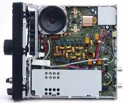
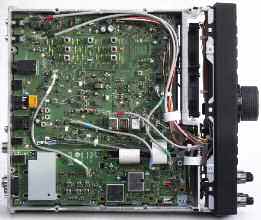 PHOTO 2: Top view with covers removed showing PA, output filters and
PHOTO 3: Underneath view showing signal processing boards.
PHOTO 2: Top view with covers removed showing PA, output filters and
PHOTO 3: Underneath view showing signal processing boards.
 a bandwidth greater than 2.7kHz makes this
The close-in strong signal performance is
limited in some cases by the AGC. A somewhat
Ukranian DX Contests. The receiver performed
complex AGC system is used, detecting signal
very wel : sensitive and lively on the quieter
level in three places within the DSP signal
bands, it coped wel picking out weak signals
amongst strong signals and QRM on the lower
channel selectivity. Hence a strong signal
PHOTO 5: The front panel hinged down showing
bands. I could not detect any real dif erence in
fal ing inside the roofing filters but stil
performance on-air between the up-conversion
outside of the final channel filter wil result
in AGC action, reducing gain and sensitivity
conditions I experienced at the time. The audio
and result in blocking. This can be heard as
quality using the internal speaker was excel ent
a quietening of the receiver from a very strong
measured for Rx1 are excel ent, similar to
signal just outside of the channel passband.
a bandwidth greater than 2.7kHz makes this
The close-in strong signal performance is
limited in some cases by the AGC. A somewhat
Ukranian DX Contests. The receiver performed
complex AGC system is used, detecting signal
very wel : sensitive and lively on the quieter
level in three places within the DSP signal
bands, it coped wel picking out weak signals
amongst strong signals and QRM on the lower
channel selectivity. Hence a strong signal
PHOTO 5: The front panel hinged down showing
bands. I could not detect any real dif erence in
fal ing inside the roofing filters but stil
performance on-air between the up-conversion
outside of the final channel filter wil result
in AGC action, reducing gain and sensitivity
conditions I experienced at the time. The audio
and result in blocking. This can be heard as
quality using the internal speaker was excel ent
a quietening of the receiver from a very strong
measured for Rx1 are excel ent, similar to
signal just outside of the channel passband.